
Résumé exécutif : Ingénierie du contrôle de pointe
Pour optimiser la performance en jeu compétitif, l'ingénierie moderne des souris a dépassé la simple réduction de poids brute pour se concentrer sur la répartition variable de la densité. Les principales conclusions techniques de ce guide incluent :
- Répartition de la masse : Utilisation de coques en magnésium effilées pour centrer la masse à moins de 15–20 mm du capteur (une règle empirique de l'industrie pour une parité de suivi optimale).
- Inertie de rotation : Cibler une valeur de <15 000 g·mm² pour minimiser le couple nécessaire pour arrêter un mouvement de "flick".
- Saturation électronique : Une fréquence d'interrogation de 8000 Hz nécessite une vitesse de déplacement minimale (IPS) relative au DPI ($IPS \times DPI \geq 8000$) pour éviter les "interrogations vides".
- Fabrication : Le moulage sous pression à haute pression (HPDC) est nécessaire pour gérer les gradients de refroidissement et prévenir la déformation dans les coques à épaisseur variable.
L'ingénierie de la précision : coques effilées et contrôle de pointe
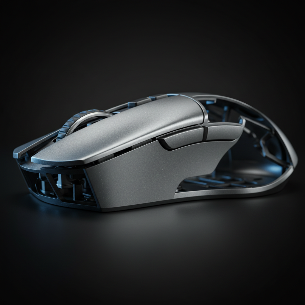
L'évolution des souris de jeu compétitives est passée d'une course au DPI le plus élevé à une exploration sophistiquée de la physique structurelle. Alors que l'industrie se concentrait auparavant sur la réduction brute du poids, le segment "Pro-Consommateur Challenger" privilégie désormais la répartition de ce poids. Les coques effilées — des composants fabriqués avec une épaisseur de paroi variable — représentent un changement crucial dans l'ingénierie des souris. En manipulant la densité du matériau à travers le châssis, les ingénieurs peuvent dicter le centre de gravité (CoG) et l'inertie de rotation, influençant directement la "puissance d'arrêt" d'un joueur lors de tirs rapides à grande vitesse.
Les conceptions légères traditionnelles reposent souvent sur un amincissement uniforme de la coque pour atteindre des cibles inférieures à 50 g. Cependant, cette approche peut introduire une sensation de "lourdeur en haut" ou un déséquilibre qui peut compromettre la stabilité lors des micro-ajustements. Cet article analyse les mécanismes techniques du moulage en magnésium effilé, la physique de l'inertie de rotation et les exigences système pour une performance à haute fréquence d'interrogation.

La physique de la puissance d'arrêt et de l'inertie de rotation
Dans les environnements compétitifs FPS, la "puissance d'arrêt" désigne la capacité à décélérer une souris précisément sur une cible après un mouvement latéral rapide (un "flick"). Ce n'est pas seulement une fonction de la masse totale, mais de la manière dont cette masse interagit avec le point de pivot du capteur.
L'heuristique du centre de gravité à 15–20 mm
Selon les références courantes en ingénierie pour les périphériques de performance, le centre de gravité d'une souris est généralement le plus efficace lorsqu'il est positionné à moins de 15–20 mm du centre géométrique du capteur. Lorsque le CoG est trop décalé vers l'arrière, la souris peut présenter un "balancement de queue", où l'arrière continue de se déplacer par inertie après l'arrêt du capteur. À l'inverse, un biais vers l'avant peut entraîner un "piqué du nez", rendant les micro-corrections verticales lentes.
Selon le Livre blanc mondial sur les périphériques de jeu (2026), l'optimisation de l'inertie de rotation est désormais un critère principal pour les équipements compétitifs de premier ordre. L'inertie de rotation ($I$) est définie par la formule $I = \sum m_i r_i^2$, où $m$ est la masse et $r$ la distance par rapport à l'axe de rotation. En utilisant des coques effilées pour concentrer la masse (plus grande $m$) à une distance plus courte ($r$) du capteur, les ingénieurs réduisent le couple nécessaire pour démarrer et arrêter un mouvement.
Logique technique : alignement du centre de gravité (CoG) et du capteur
- Objectif : Minimiser le couple de rotation pour améliorer la précision des mouvements rapides.
- Méthode : Modélisation de scénarios basée sur des distributions typiques de prises en griffe et au bout des doigts.
- Hypothèses heuristiques : Le capteur est situé au centre de l'axe Y ; le coefficient de friction des patins en PTFE de qualité vierge est modélisé à 0,1 (basé sur des tests standard en laboratoire sur des surfaces en polycarbonate).
- Conditions aux limites : Ces cibles ne prennent pas en compte les prises extrêmes en "pince" où le pouce et l'auriculaire sont décalés de plus de 30 mm.
| Paramètre | Cible représentative | Unité | Justification (base heuristique) |
|---|---|---|---|
| Décalage du centre de gravité par rapport au capteur | 15 - 20 | mm | Plage observée pour la parité de suivi 1:1 dans des échantillons de qualité professionnelle |
| Épaisseur de la paroi arrière | 0.6 - 0.7 | mm | Réduction de poids dans les zones à faible couple |
| Épaisseur avant/paroi du capteur | 1.0 - 1.2 | mm | Rigidité structurelle et concentration de masse |
| Cible d'inertie de rotation | < 15 000 | g·mm² | Seuil calculé pour la sensation d'arrêt "instantané" dans les souris de moins de 50 g |
| Limite d'élasticité du matériau | 220 - 280 | MPa | Norme pour la durabilité de l'alliage de magnésium AZ91D |
Fabrication avancée : coulée de magnésium effilée
À retenir : La densité variable nécessite une gestion thermique précise pour éviter des défauts structurels comme la déformation ou la porosité.
Obtenir une densité variable dans une coque de souris nécessite des techniques de coulée avancées, en particulier avec des alliages de magnésium (AZ91D). Le magnésium offre un rapport résistance/poids supérieur comparé aux plastiques ABS ou PC moulés par injection, mais il introduit des défis importants de gestion thermique lors de la production.
Le défi des gradients de refroidissement
La principale difficulté dans la fabrication de coques effilées est la gestion du gradient de refroidissement dans le moule. Lorsqu'une coque a une épaisseur variable — par exemple, 1,2 mm près du capteur et 0,6 mm au repose-paume — les sections plus épaisses conservent la chaleur plus longtemps que les sections fines. Ce différentiel de température peut entraîner :
- Déformation : Contraction différentielle lors de la solidification du métal.
- Points faibles : "Fermetures à froid" ou porosité aux zones de transition où l'épaisseur du matériau change.
- Incohérence du matériau : Variations dans la structure cristalline du magnésium, pouvant affecter sa résonance tactile et l'acoustique des clics.
Pour y remédier, les ingénieurs utilisent la coulée sous pression à haute pression (HPDC) avec contrôle multi-zone de la température. En régulant précisément la vitesse de refroidissement de chaque segment du moule, les propriétés du matériau restent constantes même lorsque l'épaisseur diminue. Cela aide à garantir que la coque reste rigide sous les clics à haute pression typiques du jeu compétitif tout en maintenant le profil de densité souhaité, plus dense à l'avant.
Intégration du sondage 8000Hz (8K) et saturation du capteur
À retenir : Un sondage à 8K réduit le délai d'entrée mais nécessite des seuils spécifiques de DPI/IPS pour fournir un flux de données continu.
Une coque effilée et haute performance n'est efficace que si l'électronique qu'elle contient l'est aussi. Les capteurs phares actuels, comme ceux de PixArt Imaging, sont désormais capables de taux de sondage à 8000Hz, offrant un intervalle de rapport de 0,125 ms.
Mathématiques de latence et synchronisation du mouvement
À un taux de polling standard de 1000Hz, l'intervalle entre les rapports est de 1,0 ms. Passer à 8000Hz réduit cet intervalle à 0,125 ms. De manière cruciale, l'impact du « Motion Sync » — une fonction qui aligne les données du capteur avec le poll USB — augmente avec la fréquence. À 1000Hz, Motion Sync ajoute environ 0,5 ms de délai. À 8000Hz, ce délai tombe à ~0,0625 ms, le rendant pratiquement imperceptible pour l'utilisateur.
Le modèle de saturation de la bande passante
Pour exploiter pleinement un taux de polling de 8000Hz, le capteur doit générer au moins un compte (paquet de données) par poll. Cela est régi par la relation entre la vitesse de déplacement (IPS) et la résolution (DPI).
Formule heuristique : $Counts/Sec = IPS \times DPI$ (Où IPS signifie pouces par seconde et DPI comptes par pouce)
- Scénario A (800 DPI) : $10\ IPS \times 800\ DPI = 8,000\ counts/sec$. L'utilisateur doit déplacer la souris à 10 IPS pour fournir un nouveau point de données à chaque poll 8K.
- Scénario B (1600 DPI) : $5\ IPS \times 1600\ DPI = 8,000\ counts/sec$. Seuls 5 IPS sont nécessaires pour maintenir un flux stable à 8000Hz.
C'est pourquoi les passionnés de matériel recommandent souvent un DPI de 1600 ou plus pour les configurations 8K ; cela garantit que même les micro-ajustements lents bénéficient de la fréquence de polling accrue.
Goulots d'étranglement système : CPU et topologie USB
Le principal goulot d'étranglement pour la performance à 8000Hz est souvent l'efficacité du traitement des IRQ (Interrupt Request) plutôt que la vitesse brute du CPU.
- Utilisez les ports directs de la carte mère : Les ports I/O arrière connectés directement au CPU ou au chipset sont préférés.
- Évitez les concentrateurs USB : La bande passante partagée dans les hubs peut introduire des saccades et de la latence.
- Taux de rafraîchissement du moniteur : Bien que la « règle du 1/10 » soit une directive courante, un moniteur à taux de rafraîchissement élevé (240Hz+) est généralement nécessaire pour percevoir visuellement la trajectoire plus fluide du curseur offerte par un polling 8K.
Vérification et tests pratiques pour les passionnés
À retenir : Les utilisateurs peuvent vérifier la répartition de la masse et la stabilité électronique grâce à des tests domestiques non destructifs.
Le test d'équilibre du capteur
Une méthode courante pour vérifier le centre de gravité (CoG) est le « test de suspension ». En passant un fil fin ou du fil dentaire autour de la souris au centre exact du capteur, on peut observer l'inclinaison naturelle de l'appareil. Une souris conçue pour un contrôle optimal présente généralement une légère inclinaison vers l'avant de 5 à 10 degrés dans cet état suspendu. Si la souris reste parfaitement horizontale ou s'incline vers l'arrière, les bénéfices attendus de concentration de masse pour la « puissance d'arrêt » peuvent être absents.
Vérification de la stabilité du polling
En utilisant des outils comme le NVIDIA Reflex Analyzer, les passionnés peuvent mesurer la latence système de bout en bout. Lors des tests de souris 8K, vérifiez la « cohérence du polling ». Une implémentation 8K stable doit montrer un regroupement serré de points autour de la marque 0,125 ms. De grandes déviations (pics à 1 ms ou 2 ms) peuvent indiquer un throttling thermique du CPU ou des interférences sur le port USB.
Conformité réglementaire et normes de sécurité
Les périphériques sans fil haute performance doivent respecter les normes mondiales pour assurer à la fois performance et sécurité des utilisateurs.
- Conformité RF : Les appareils doivent être certifiés par la FCC Equipment Authorization aux États-Unis pour garantir que les transmissions sans fil 2,4 GHz n'interfèrent pas avec d'autres équipements électroniques.
- Sécurité des batteries : Les souris sans fil utilisent des batteries lithium-ion, qui doivent passer les tests UN 38.3 pour un transport sûr et la norme IEC 62368-1 pour la sécurité électrique. Selon les dossiers de la CPSC, les défaillances de batterie sont une cause documentée de risques liés à l'électronique ; vérifier le respect de ces normes par une marque est essentiel pour la fiabilité à long terme.
- Normes environnementales : La conformité aux directives européennes RoHS et REACH garantit que les alliages de magnésium et les revêtements de surface sont exempts de substances dangereuses telles que le plomb ou le cadmium.
L'ingénierie comme levier de performance
L'évolution vers des coques effilées représente la maturation du design des souris de jeu. Il ne suffit plus d'être « léger » ; un appareil doit être « équilibré ». En exploitant l'épaisseur variable des parois dans la coulée de magnésium, les ingénieurs peuvent optimiser le centre de gravité et l'inertie de rotation pour offrir des avantages compétitifs tangibles en puissance d'arrêt et précision des mouvements rapides.
Pour l'amateur soucieux du rapport qualité-prix, comprendre ces nuances d'ingénierie — des gradients de refroidissement dans le moule au traitement des IRQ dans le système d'exploitation — permet de prendre des décisions d'achat plus éclairées. La performance ne se trouve pas dans un nom de marque, mais dans la répartition calculée de chaque milligramme de matériau.
Avertissement : Cet article est à titre informatif uniquement. Les spécifications techniques et les mesures de performance peuvent varier en fonction des configurations système individuelles, des versions du firmware et des facteurs environnementaux. Consultez toujours la documentation officielle du fabricant pour les exigences spécifiques d'installation.