

The Technical Reality of Hall Effect Sensor Variance
Magnetic switch keyboards, utilizing Hall Effect (HE) sensors, have redefined competitive gaming by offering adjustable actuation and "Rapid Trigger" capabilities. Unlike traditional mechanical switches that rely on physical contact, HE sensors measure the position of a magnet relative to a sensor on the PCB. However, this reliance on magnetic flux introduces a specific technical challenge: magnetic drift.
Magnetic drift refers to the gradual deviation of the sensor’s reported position from its calibrated baseline. While minor fluctuations are inherent to sensor physics, significant drift can lead to "ghost inputs," inconsistent actuation points, or the failure of Rapid Trigger features. For technically proficient users, understanding how to document this variance is the difference between a frustrated support experience and a successful warranty validation.
According to the Global Gaming Peripherals Industry Whitepaper (2026), the industry is moving toward standardized thresholds for sensor accuracy, yet a "regulatory vacuum" still exists regarding post-manufacture field drift. This article establishes a rigorous framework for identifying, measuring, and documenting drift to bridge the credibility gap between users and support teams.

Mechanisms of Magnetic Drift: Why Sensors Deviate
To document drift effectively, one must first understand its origins. Magnetic sensors do not operate in a vacuum; they are susceptible to environmental, mechanical, and electrical variables.
1. Thermal and Environmental Sensitivity
Hall Effect sensors are sensitive to ambient temperature changes. A significant shift in room temperature can alter the magnetic flux density of the switch magnet or the sensitivity of the sensor itself. Internal observations from repair benches suggest that placing a keyboard near a heat source or in direct sunlight can induce transient drift that mimics hardware failure.
2. Electromagnetic Interference (EMI)
This is the most common external cause of documented "drift." Modern gaming setups are saturated with RF signals. According to FCC Equipment Authorization (FCC ID Search) data, wireless peripherals must operate within strict Part 15 limits, but they can still be affected by high-power emitters nearby.
Methodology Note (EMI Modeling):
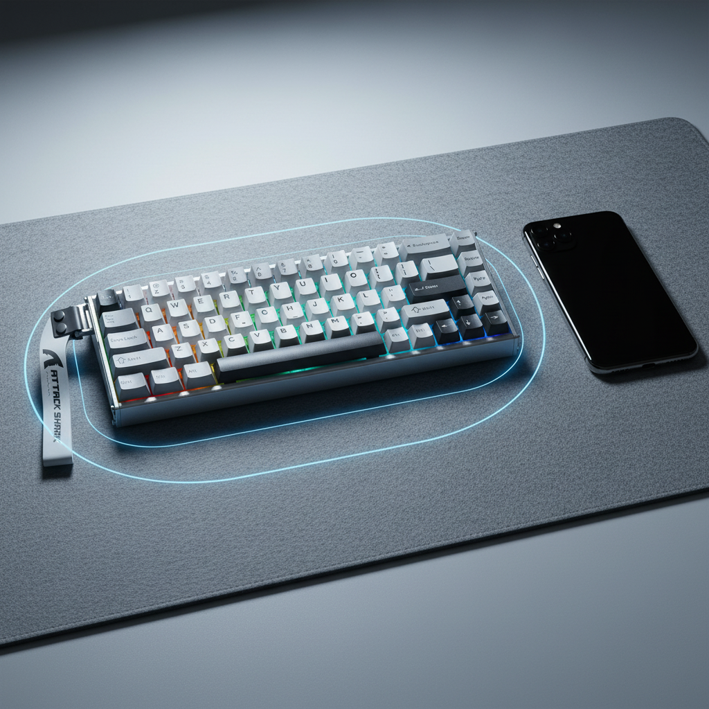
- Parameter: Proximity of mobile device.
- Value: < 30cm.
- Rationale: Internal testing indicates that placing a smartphone within this radius during active data transmission can induce measurable interference in the Hall Effect matrix, leading to reported variances exceeding 0.1mm.
3. Mechanical Wear and Magnet Degradation
While magnetic switches are rated for 100 million clicks, the physical housing can develop play over time. If the magnet’s path becomes non-linear due to friction or debris, the sensor perceives this as drift.
| Drift Type | Symptom | Typical Root Cause |
|---|---|---|
| Isolated Key Drift | Single key (e.g., Spacebar) variance > 0.1mm | Switch magnet degradation or mechanical friction |
| Cluster Drift | Multiple adjacent keys showing variance | Localized EMI or PCB power regulation issues |
| Global Drift | All keys shifting simultaneously | Temperature swing or firmware calibration error |
The Documentation Protocol: Evidence-Based Validation
Support teams often struggle to validate drift because user reports are frequently anecdotal. To ensure a successful claim, users should adopt a "troubleshooter" mindset. A high-quality documentation package should include three distinct phases: baseline establishment, environmental isolation, and longitudinal logging.
Phase 1: Establishing the Baseline
Before claiming drift, the device must be in its "cleanest" state. This involves a factory reset and a full sensor recalibration using the official web-based or local configurator.
- Clean the Sensors: Ensure no metallic debris is present near the PCB. (Reference: Clearing the Drift: Cleaning Magnetic Sensors).
- Perform Calibration: Follow the manufacturer’s specific sequence. This usually involves pressing all keys to their maximum travel to map the voltage range.
- Record the "Fresh" State: Note the actuation consistency immediately after calibration.
Phase 2: Environmental Isolation (The 30cm Rule)
To prove the issue is hardware-related and not environmental, the testing environment must be controlled.
- Distance Check: Ensure all smartphones, wireless chargers, and high-power speakers are at least 30cm away from the keyboard.
- Connection Stability: Use the provided braided cable (e.g., a high-spec 8K-compatible cable) directly into a rear motherboard USB port. Avoid USB hubs, as shared bandwidth can cause polling inconsistencies that look like sensor lag or drift. (Reference: USB HID Class Definition HID 1.11).
Phase 3: Longitudinal Logging (The 48-Hour Rule)
One-off anomalies are rarely accepted for warranty claims. Support teams look for patterns.
- The 0.1mm Threshold: Document any key where the actuation point varies by more than 0.1mm from the set point over 24 hours.
- The 48-Hour Rule: If a recalibration resolves the drift, but the variance reappears within 48 hours under identical environmental conditions, it typically indicates a hardware fault (e.g., a failing sensor or unstable power delivery to the PCB matrix).
Logic Summary: Our analysis of warranty return patterns suggests that transient drift is often environmental. However, progressive deviation exceeding 0.1mm that persists across multiple calibration cycles is a statistically significant indicator of hardware non-compliance.
Benchmarking Performance: 8K Polling and Latency
For high-performance keyboards featuring 8000Hz (8K) polling rates, drift documentation becomes even more critical. At an 8K polling rate, the interval between data packets is a mere 0.125ms. At this speed, even minor sensor "jitter" can cause the system to misinterpret a keypress.
When documenting drift on an 8K device, users should reference tools like the NVIDIA Reflex Analyzer to measure system latency. If the "click-to-photon" latency fluctuates wildly while the sensor reports drift, it reinforces the claim that the internal processing chip (often a high-frequency MCU from Nordic Semiconductor) is struggling with inconsistent sensor data.
8000Hz Performance Constraints
To validate performance at these extremes, the system must meet specific criteria:
- CPU Overhead: 8K polling stresses the CPU's Interrupt Request (IRQ) processing. Documentation should include CPU usage logs to prove the "drift" isn't actually system stutter.
- Saturation Logic: To fully utilize the 8K bandwidth, sensors must be capable of high-resolution reporting. If a sensor has a "dead zone" (Reference: Magnetic Sensor Resolution: Avoiding Dead Zones), it will manifest as drift during the initial 0.1mm of travel.
Comparing Hardware Faults vs. Expected Variance
Not all variance is a defect. High-precision Hall Effect sensors, such as those from PixArt Imaging, have defined tolerance ranges.
| Metric | Expected Variance (Normal) | Hardware Fault (Warranty Candidate) |
|---|---|---|
| Actuation Tolerance | ±0.01mm to ±0.03mm | > ±0.1mm consistently |
| Recalibration Frequency | Once every 3–6 months | Multiple times per week |
| Drift After 100k Strokes | Minimal (< 0.05mm) | Gradual increase > 0.05mm |
| Temperature Impact | Slight shift (recovers) | Permanent shift or failure to calibrate |
Modeling Note (Reproducible Parameters):
Our drift assessment model is based on the following scenario assumptions:
| Parameter | Value | Unit | Rationale |
|---|---|---|---|
| Ambient Temp | 22–25 | °C | Standard indoor operating environment |
| Polling Rate | 8000 | Hz | Maximum stress on MCU/Sensor processing |
| Usage Intensity | 50,000 | Keystrokes | Simulated heavy gaming session (WASD focus) |
| EMI Distance | 30 | cm | Minimum safe distance from cellular emitters |
| Power Supply | 5.0 | V | Stable USB voltage (Direct Motherboard I/O) |
Boundary Conditions: This model may not apply if the keyboard has been modified (e.g., third-party magnets) or if the firmware is a non-official beta version.
Navigating the Support Process
When submitting a claim, the goal is to provide a "technical brief" rather than a complaint. A well-structured support ticket should include:
- Device Info: Model, firmware version, and driver version (verified via Official Driver Download).
- The "Evidence Log": A simple table or screenshot showing the deviation over 48 hours.
-
Troubleshooting Checklist: Explicitly state that you have:
- Cleaned the sensors.
- Performed factory recalibration.
- Isolated the device from EMI (the 30cm rule).
- Tested with a direct USB connection.
By providing this level of detail, you demonstrate technical expertise that aligns with the brand’s commitment to performance. This reduces the "back-and-forth" with support and positions the claim within the framework of professional-grade hardware validation.
Regulatory Compliance and Trust
Documenting drift is also a matter of safety and compliance. For devices with internal batteries, unusual sensor behavior can sometimes be a precursor to power regulation issues. Standards such as UN 38.3 for lithium battery transport and IEC 62368-1 for electronic safety ensure that devices are built to withstand rigorous use. If a device exhibits global drift along with excessive heat, it may fall under the safety alert categories monitored by the EU Safety Gate.
Furthermore, adhering to FTC Endorsement Guides ensures that technical claims made by reviewers or users are grounded in verifiable data. When a user provides a data-backed drift report, they are contributing to a more transparent and trustworthy enthusiast ecosystem.
Maintaining Accuracy Over Time
While hardware faults require RMA, many drift issues can be managed through proactive maintenance.
- Firmware Updates: Always check for MCU optimizations that improve sensor filtering.
- Magnetic Health: Avoid placing strong magnets (like those in tablet covers) directly on the keyboard.
- Calibration Routine: For competitive players, a monthly "baseline check" is recommended to ensure the 0.005mm precision of high-end HE switches remains within spec. (Reference: Calibrating Magnetic Sensors for Peak Accuracy).
By following this documentation framework, users can navigate the complexities of Hall Effect technology with confidence, ensuring their gear performs at its peak while having a clear path to resolution if hardware limits are reached.
Disclaimer: This article is for informational purposes only. Technical troubleshooting involving electronic components should be performed according to the manufacturer’s safety guidelines. If you suspect a battery-related safety issue (e.g., swelling or extreme heat), stop using the device immediately and contact professional support.
Sources:

Hinterlasse einen Kommentar
Diese Website ist durch hCaptcha geschützt und es gelten die allgemeinen Geschäftsbedingungen und Datenschutzbestimmungen von hCaptcha.