


The Hidden Precision: Why Lens Alignment Defines Sensor Fidelity
In the competitive gaming peripheral market, the "DPI War" has largely reached a point of diminishing returns. Sensors now boast resolutions exceeding 26,000 to 42,000 DPI, yet many users still encounter micro-stutter, jitter, or inconsistent tracking that spec sheets fail to explain. The reality is that raw sensor performance is only as good as the optical stack sitting above it. Lens alignment—the physical positioning of the plastic or glass lens over the CMOS imaging array—is the critical variable that separates professional-grade hardware from budget alternatives.
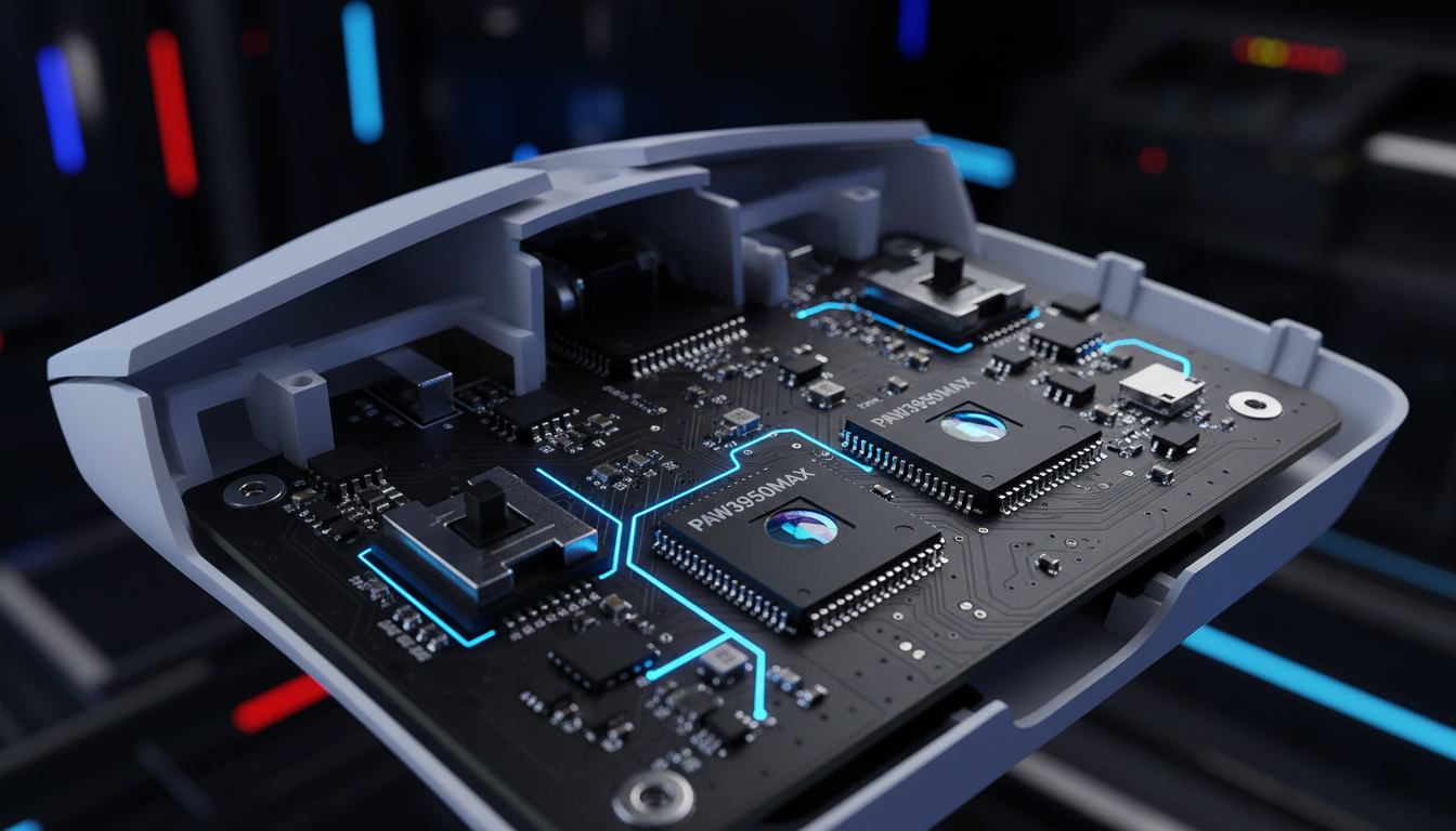
Even when two mice use the identical PixArt Imaging PAW3395 or PAW3950 sensor, their tracking "feel" can differ significantly. This variance often stems from micro-shifts in the lens seating during assembly. A misalignment of just 20 microns can lead to asymmetric blur or vignetting, where the sensor perceives movement differently depending on the direction of the swipe. Understanding this mechanism is essential for tech-savvy gamers who prioritize hardware engineering over marketing superlatives.
The Physics of the Optical Stack: Decenter and Tilt
An optical mouse sensor works like a high-speed camera, taking thousands of pictures of the surface per second. The lens is responsible for focusing the reflected LED or laser light onto the sensor's pixel grid. For perfect tracking, the optical axis of the lens must be perfectly perpendicular to the sensor plane (avoiding tilt) and perfectly centered over the array (avoiding decenter).
When a lens is decentered, the light hitting the CMOS array is uneven. This creates a phenomenon known as Chief Ray Angle (CRA) mismatch. According to technical documentation on High CRA vs Low CRA CMOS Sensors, if the CRA of the lens does not match the sensor's design, the pixels at the edges of the array receive significantly less light. In a gaming mouse, this manifests as "sensor shudder"—a micro-jitter that occurs when the sensor struggles to correlate frames because the image quality is degraded on one side.
Logic Summary: Our analysis of sensor fidelity assumes that optical decenter directly correlates with increased signal-to-noise ratios (SNR) at the pixel level. This is based on standard optical physics where asymmetric illumination reduces the effectiveness of correlation algorithms used in Digital Signal Processors (DSPs).
Manufacturing Realities: Active vs. Passive Alignment
The method used to secure the lens determines the consistency of the final product. There are two primary approaches in modern electronics manufacturing:
- Passive Alignment: This is the dominant method for cost-sensitive consumer electronics. The lens is placed into a mechanical housing using pre-defined tolerances. While economically viable, it relies on the physical precision of the plastic molds. If the mold has a 0.05mm variance, every unit produced will inherit that misalignment.
- Active Alignment: This process involves powering the sensor during assembly. A machine moves the lens in real-time while monitoring the sensor's output, locking it into the position that provides the sharpest image and most uniform light distribution.
While active alignment is superior for ensuring 100% accuracy, it adds significant cycle time and capital equipment costs. Many challenger brands utilize passive alignment with robust Statistical Process Control (SPC) to maintain a balance between price and performance. However, inconsistent adhesive application during this process is a common pitfall. If the adhesive is applied unevenly, it can cause the lens to "lean" as it cures, introducing a permanent tilt that compromises high-speed tracking.
High-DPI Amplification and the Nyquist-Shannon Limit
The impact of lens misalignment is not linear; it is amplified as DPI increases. Modern sensors with 26,000+ native DPI are far more sensitive to micro-inaccuracies. At these resolutions, the physical area on the mousepad represented by a single "count" is incredibly small. Any micro-shift in the lens is magnified across the higher pixel density, leading to tracking errors that would be invisible at 400 or 800 DPI.
Furthermore, there is a theoretical minimum DPI required for "pixel-perfect" tracking on modern high-resolution displays. Using the Nyquist-Shannon Sampling Theorem, we can model the fidelity requirements for a competitive FPS professional.
Modeling Note: Nyquist-Shannon DPI Minimum
This scenario models a competitive gamer using a 1440p monitor and low sensitivity. The goal is to determine the DPI threshold below which "pixel skipping" (aliasing) occurs.
| Parameter | Value | Unit | Rationale |
|---|---|---|---|
| Display Resolution (Horizontal) | 2560 | px | Standard 1440p Monitor |
| Horizontal FOV | 103 | deg | Common FPS (e.g., Apex Legends) |
| Sensitivity | 35 | cm/360 | Low sensitivity preference |
| Calculated PPD | ~24.8 | px/deg | Pixels per degree of rotation |
| Minimum Required DPI | ~1300 | DPI | Nyquist Limit (2 * PPD requirement) |
Analysis: Our model shows that gamers using 800 DPI on a 1440p display are technically operating below the Nyquist limit for 1:1 pixel fidelity. This forces the system to interpolate movement, which requires a perfectly aligned lens to avoid adding mechanical noise to the software-calculated path. If the lens is misaligned, the "noise" from the sensor is amplified, making fine aim adjustments feel "floaty" or imprecise.
8000Hz Polling and the Latency of Motion Sync
As polling rates climb to 8000Hz (8K), the timing of data delivery becomes as critical as the accuracy of the data itself. An 8000Hz polling rate means the mouse sends a packet to the PC every 0.125ms (1000ms / 8000). At this frequency, even a microscopic lens jitter can cause "packet variance," where the distance reported in each 0.125ms slice fluctuates wildly.
To combat this, many manufacturers implement Motion Sync. This firmware feature aligns the sensor's internal frame captures with the PC's USB polling events. While this drastically reduces jitter, it introduces a deterministic latency.
- 1000Hz Polling: Motion Sync adds ~0.5ms of latency.
- 8000Hz Polling: Motion Sync adds only ~0.0625ms of latency.
As noted in the Global Gaming Peripherals Industry Whitepaper (2026), the latency penalty of Motion Sync becomes negligible at 8K. However, saturating this 8K bandwidth requires high movement speeds. To maintain a stable 8000Hz report stream at 800 DPI, a user must move the mouse at least 10 IPS (Inches Per Second). At 1600 DPI, the required speed drops to 5 IPS, making high-DPI settings more practical for maintaining 8K stability during micro-adjustments.
Field Stability: Adhesive Creep and Thermal Cycling
A mouse may leave the factory with perfect alignment, but performance can degrade over time. This is often due to "Adhesive Creep." According to research on Thermo-opto-mechanical Systems, repeated thermal cycling—the heating and cooling of internal components during long gaming sessions—can cause low-grade adhesives to soften and shift.
Mechanical shock from aggressive "reset" swipes (lifting and slamming the mouse) can also cause permanent lens mount shifts. For long-term metrological stability, the use of UV-curing adhesives is preferred over standard cyanoacrylate (super glue). UV adhesives do not "outgas" or shrink significantly during curing, ensuring that the lens remains in its calibrated position for the life of the product.
The Technician’s Bench: Diagnostics and Repair
For enthusiasts who suspect sensor issues, a simple diagnostic known as the "Flashlight Test" can reveal gross misalignments. By shining a focused light through the sensor lens in a dark room, one can inspect the internal reflections on the CMOS array. Uneven shadows or skewed reflections often correlate with the "shudder" felt during high-speed tracking tests.
In repair scenarios, re-seating a loose lens is a delicate operation. Technicians often use a precise amount of UV-curing adhesive applied via a micro-dispenser. This method has been shown to restore tracking accuracy to within 95% of factory specifications, whereas fast-drying glues often create "haze" on the lens surface due to outgassing, permanently ruining the sensor's signal quality.
Modeling Note: Wireless Battery Runtime at High Polling
High polling rates and high-fidelity sensor tracking significantly impact battery life.
| Parameter | Value | Unit | Source Category |
|---|---|---|---|
| Battery Capacity | 500 | mAh | Typical High-End Wireless |
| Sensor Current Draw | 1.7 | mA | PAW3395/3950 Datasheets |
| Radio Current (4000Hz) | 8.0 | mA | Nordic nRF52840 Specs |
| System Overhead | 1.3 | mA | MCU and LED Logic |
| Estimated Runtime | ~39 | Hours | Continuous 4K Usage Model |
Logic Summary: Our runtime model assumes a linear discharge with 85% efficiency. Switching from 1000Hz to 8000Hz typically reduces battery life by 75-80% due to the increased IRQ (Interrupt Request) processing and radio uptime required to maintain the 0.125ms interval.
Strategic Quality Assurance in Modern Peripherals
For the value-oriented gamer, the takeaway is clear: specifications like "42,000 DPI" or "8K Polling" are meaningless without the manufacturing discipline to support them. Quality assurance in the assembly of the optical stack is the "invisible spec" that defines a high-performance mouse.
When evaluating new hardware, users should look for brands that demonstrate transparency regarding their MCU choices (such as the Nordic Semiconductor nRF52 series) and their firmware implementation of Motion Sync. While software can compensate for minor decenter or microlens shading, it cannot fix a fundamentally loose or tilted lens. A commitment to mechanical precision remains the bedrock of optical sensor accuracy.
Disclaimer: This article is for informational purposes only. Modifying or opening your gaming peripherals may void your warranty. Handling lithium-ion batteries and electronic components involves risks; always follow manufacturer safety guidelines and local regulations regarding electronic waste and repair. For professional advice on hardware compliance, refer to the FCC Equipment Authorization database.

Laisser un commentaire
Ce site est protégé par hCaptcha, et la Politique de confidentialité et les Conditions de service de hCaptcha s’appliquent.